
SWLS488 Guide
Roller Team Control Panel Guide
Everything you need to know about the SWLS488 – S1123 control panel, from daily use and battery monitoring to water levels, lighting and common checks.
Using the control panel
This guide focuses on the Roller Team Control Panel (SWLS488), explaining what each A–H control does and how to read the key battery, temperature and tank information during everyday motorhome use.

Roller Team Control Panel (SWLS488)
The SWLS488 is the main control hub for your habitation area. It lets you manage lighting, water, battery information and tank levels from one central panel, making it one of the most useful systems to understand when you first start using your motorhome.
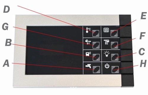
Roller Team Control Panel (SWLS1123)
The SWLS1123 panel layout adds extra symbol indicators while still giving you quick access to power, battery and system information during day-to-day motorhome use.
A – Water Pump
Water pump on/off. When it comes to managing resources in a motorhome, the decision of whether to leave the water pump on or off is an important consideration, each with pros and cons.
Pros
- Immediate access to water: Keeping the water pump on ensures that you have instant access to running water whenever you need it. This is particularly useful for washing hands, cooking and cleaning dishes.
- Convenience: With the water pump on, you will not have to repeatedly switch it on and off each time you require water. This can make daily tasks more efficient and reduce the hassle of constant adjustments.
- Prevention of contamination: Leaving the pump on can help prevent the growth of bacteria and mould in the water lines. The constant circulation of water discourages stagnation and helps maintain better water quality.
Cons
- Power consumption: Keeping the water pump running continuously can lead to increased power consumption, potentially draining the motorhome battery more quickly. This can be a concern when wild camping or staying without electrical hook-up.
- Noise: Water pumps can be noisy, and leaving the pump on may create a constant background noise inside the motorhome. This can be a nuisance during quiet times or while sleeping.
- Possible flooding: In the event of a burst pipe or water leak, the pump could continue to push out all available water.
B – External Light
This is a simple on/off switch for the outside light, normally positioned just above the habitation door. It helps create a more inviting entrance and is often used to illuminate the awning area in the evening.
C – Internal Lights
This is the main on/off switch for the inside lights. It also activates the 12-volt supply used by many other power points within the habitation area, such as TV points when running on 12 volts. In many cases this is left on while using your motorhome, with the individual lights then controlled by their own switches.
D – Internal / external Temperature
Press the button to display the internal temperature marked IN. Press it again to display the external temperature marked OUT. If OPT appears, the external sensor is not present. If the temperature sensor is faulty, – will appear. The display remains visible for about 30 seconds.
E – Fresh – Waste Water Levels
Press the button several times to display the tank levels as a percentage for the tanks identified by the symbols S1, R1 and R2. If S1 is empty or R1 or R2 are full, the display will flash. If the connection to the tank is faulty, — will be shown. S1 is the fresh water tank, R1 is waste tank 1 and R2 is waste tank 2, although not all motorhomes have the second waste tank. The display remains visible for about 30 seconds.
F – Habitation Battery
Press this button once to display the service or habitation battery voltage. Press it again to display the remaining charge as a percentage. The display remains visible for about 30 seconds.
G – Vehicle Battery
Press this button once to display the start-up or vehicle battery voltage. Press it again to display the remaining charge as a percentage. The display remains visible for about 30 seconds.
H – On/Off
Press once to turn the panel on. Press again to turn it off.
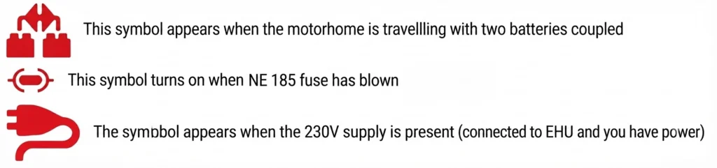
Other Roller Team Control Unit Information
NE 268,NE 269,NE 185_11 T
Control Panel – NE268, NE269, NE185
Control Panel NE 268,NE 269,NE 185_11 T, these control panels are very commonly used on the Roller Team Range. Download
Control Wiring NE NE185, 154, 152, 188, 148, 185, 143
Control Panel – NE185, 154, 152, 188, 148, 185, 143 – Wiring Diagram
Control Wiring NE NE185, 154, 152, 188, 148, 185, 143, these control panels are very commonly used on the early Roller Team Range. Wiring Diagram. Download.
Control Panel – NE100
Control Panel – NE100
Control Panel NE 100, these control panels are very commonly used on the early Roller Team Range. Download.
Control Panel – NE196
Control Panel – NE196
Control Panel NE 196, these control panels are very commonly used on the early Roller Team Range.
More Downloads Soon
This final space can be used for a future control unit resource when it is ready to add.